
Reference chart
All eleven geometric characteristics, each with its symbol, drawing callout, tolerance zone and inspection setup, plus datums, feature control frames and the material condition modifiers. Written to ASME Y14.5-2018.
Free download
Get the GD&T cheat sheet as a PDF.
The whole cheat sheet on a single page, drawn at poster scale so the symbols stay readable pinned above a desk.
Downloading takes a free Drafter account. One account gets you every chart in the toolbox.

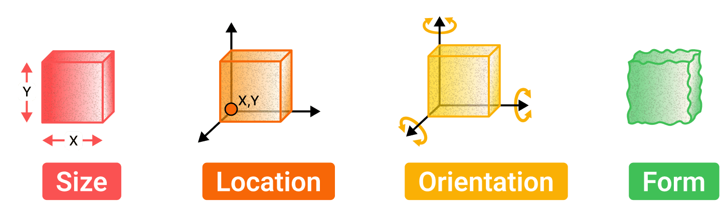
GD&T is a symbolic language used in engineering drawings to define the allowable variations in the geometry of parts and assemblies. GD&T controls four characteristics of your given part: size, location, orientation and form (SLOF).
Every characteristic further down this page is one of those four, or a combination of them. The coloured badge on each card says which, in the same four colours as the cubes here.

Datums are theoretical axes, planes, or points used as fixed references for manufacturing and inspection. They are derived from datum features, the actual physical surfaces or features on the part.
The datum feature symbol shown here is how one gets named on a drawing: a letter in a box on a leader, with the filled triangle touching the surface the letter refers to.
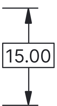
The theoretically exact dimension used to define the size, location, or orientation of a feature. Basic dimensions are used to indicate distance or angles that are controlled by the GD&T symbol in a feature control frame.
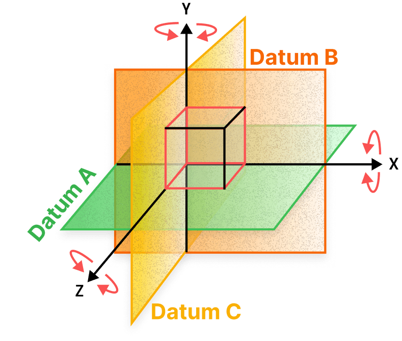
Effective datums create a datum reference frame that can constrain up to 6 degrees of freedom (DOF). These are chosen based on features most critical to the part’s function.
Six is three translations and three rotations, one of each about X, Y and Z, which is what the three axes and three curved arrows in the diagram are counting off.
The order the datums are called in matters as much as which ones they are: each one takes away what the one before it left free, which is why a feature control frame reads its datums left to right.
| Datum | What it typically constrains |
|---|---|
| Primary | Typically a surface or feature of size that constrains three or four degrees of freedom. |
| Secondary | Typically a secondary surface or feature of size that controls two more degrees of freedom. |
| Tertiary | Typically the final surface or feature, fully constraining all six degrees of freedom. |
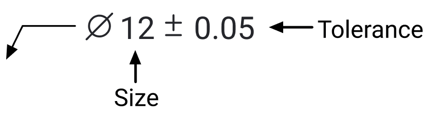
A part feature with a measurable dimension, like a hole, slot, pin, or tab, which can often be measured directly using calipers. It defines size limits, and form (if not further refined) of the feature. A feature of size is required to use MMC or LMC.
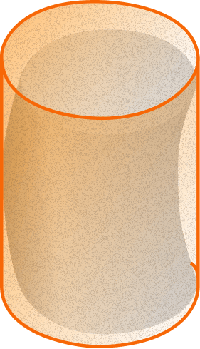
The surfaces of a feature of size shall not extend beyond a boundary (envelope) of perfect form at maximum material condition (MMC). For example, a part at its largest size limit must be perfectly shaped, like a cylinder being round and straight at MMC, to ensure proper fit and function.
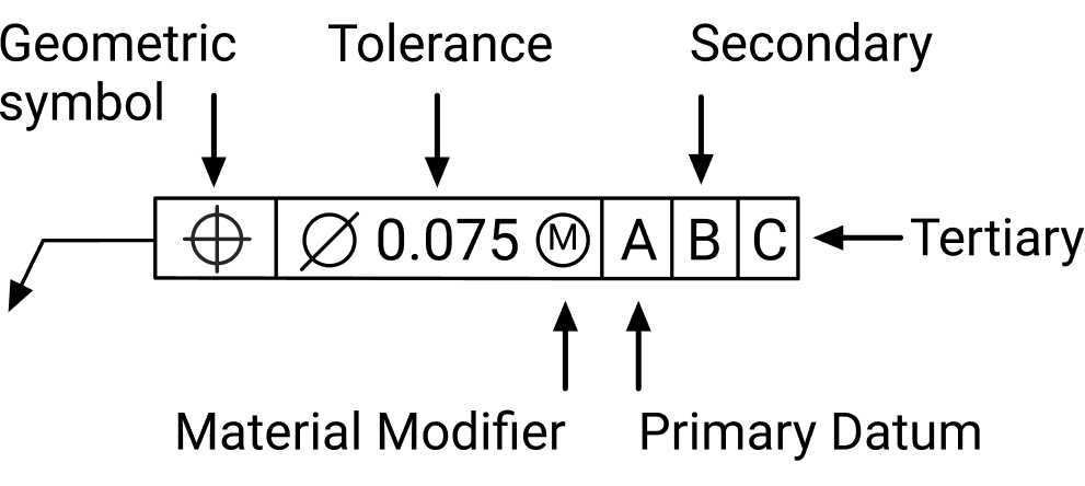
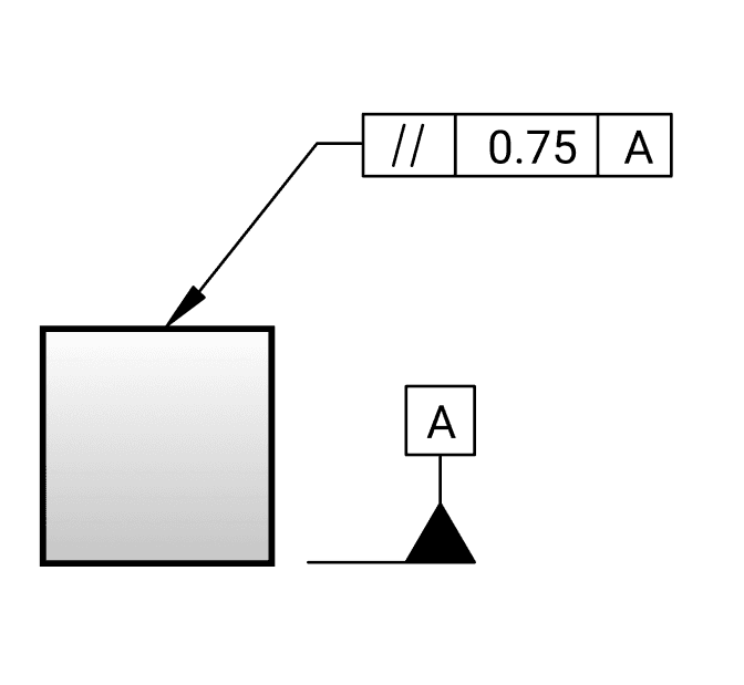
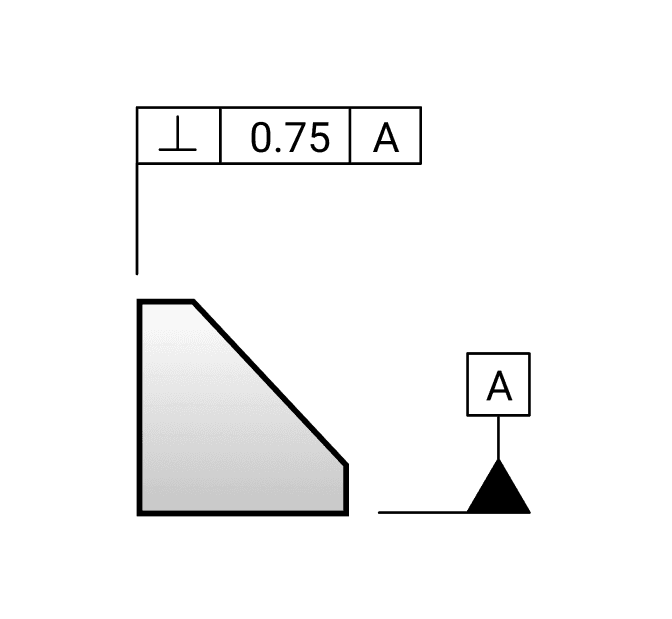
One frame, read left to right, is the whole instruction: which characteristic is controlled, how much of it is allowed, and what it is measured from. Every card in the sections below shows the same frame drawn onto a real part.
Not every compartment appears every time. A form characteristic references no datum at all, so its frame stops after the tolerance, and a material modifier only appears where the control applies to a feature of size. The diameter symbol in front of a tolerance is worth reading carefully: it says the zone is a cylinder rather than two parallel planes.
| Compartment | What it specifies |
|---|---|
| Geometric symbol | Which of the eleven characteristics is being controlled. |
| Tolerance | How big the tolerance zone is, with a diameter symbol in front of it where the zone is cylindrical. |
| Material modifier | MMC or LMC, where the tolerance is allowed to grow as the feature departs from that condition. Needs a feature of size. |
| Primary datum | The first reference the feature is measured from. |
| Secondary datum | The second, constraining what the primary left free. |
| Tertiary datum | The third, constraining what is still left. |
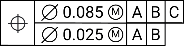
One geometric symbol against two stacked segments. The upper segment locates the pattern; the lower one tightens how the features sit relative to each other without relocating them.
| Segment | What it controls |
|---|---|
| Upper segment | Controls location and orientation between features. Constrains translation and rotational DOF around the datum reference frame. |
| Lower segment | Refines orientation between features. Constrains only rotation to the datum reference frame. |
Check items off as you go. Nothing here is saved: it resets the next time you open the page.
| Step | What to do | |
|---|---|---|
| Add and fill all relevant specifications and company information. | ||
| Place as few views as are required to show all critical features. | ||
| Identify all pertinent datums that orient and constrain the part in up to 6 DOF. | ||
| Add GD&T symbols and tolerances to all datums and features that require precise control. | ||
| Apply dimensions to all critical features and datums. | ||
| Add any surface finishes, threaded holes, and so on. | ||
| Add any critical information not represented in the drawings. |
Shape on its own terms. None of these four reference a datum: they ask whether the feature is the shape it claims to be, wherever it happens to sit.
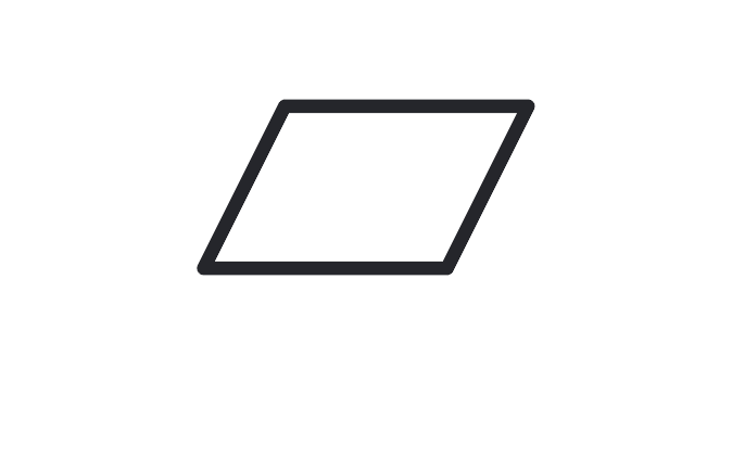
Flatness in GD&T is a form tolerance that ensures a surface is flat without reference to a datum feature. The views below show surface control. Flatness can also apply to a feature of size, where the derived median plane is controlled.
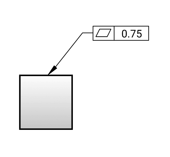
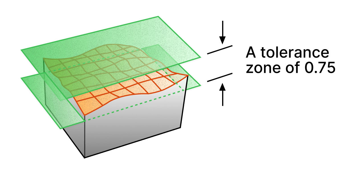
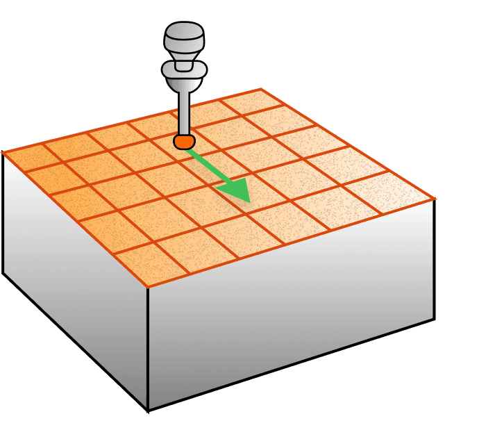
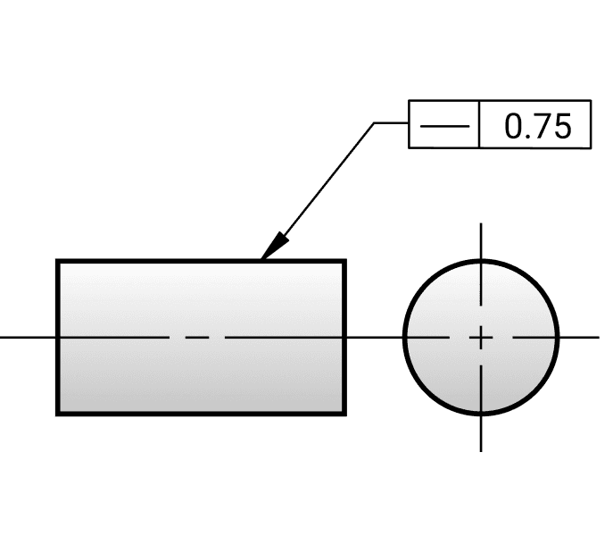
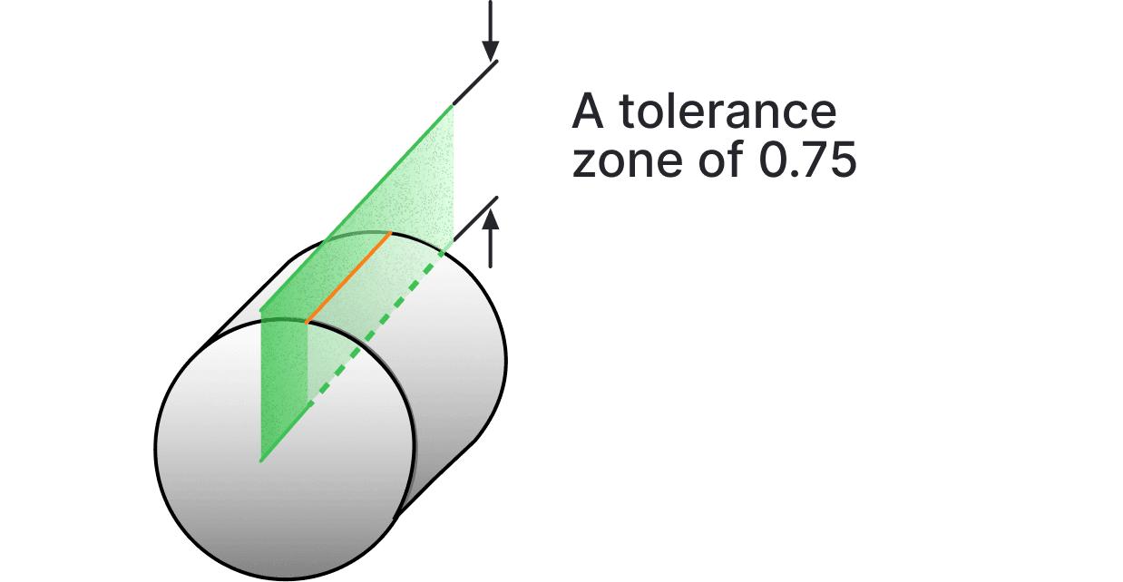
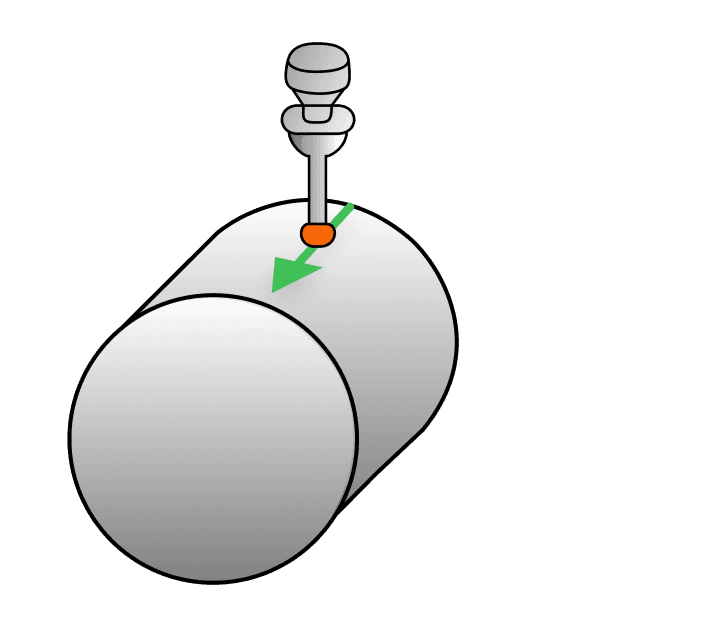
Straightness in GD&T is a form tolerance that can be applied to ensure either a surface remains uniformly linear or the axis of a feature remains straight. It can be called out on a surface feature or the axis of a cylindrical feature, depending on the specific application. The views below show surface control. Straightness can also apply to a feature of size, where the derived median line is controlled.

Circularity in GD&T is a form tolerance used to control how close a feature’s cross section is to a perfect circle. It applies to individual circular elements of a surface and is evaluated independently at each cross section, without reference to any datum.
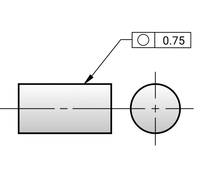
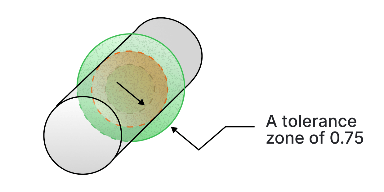
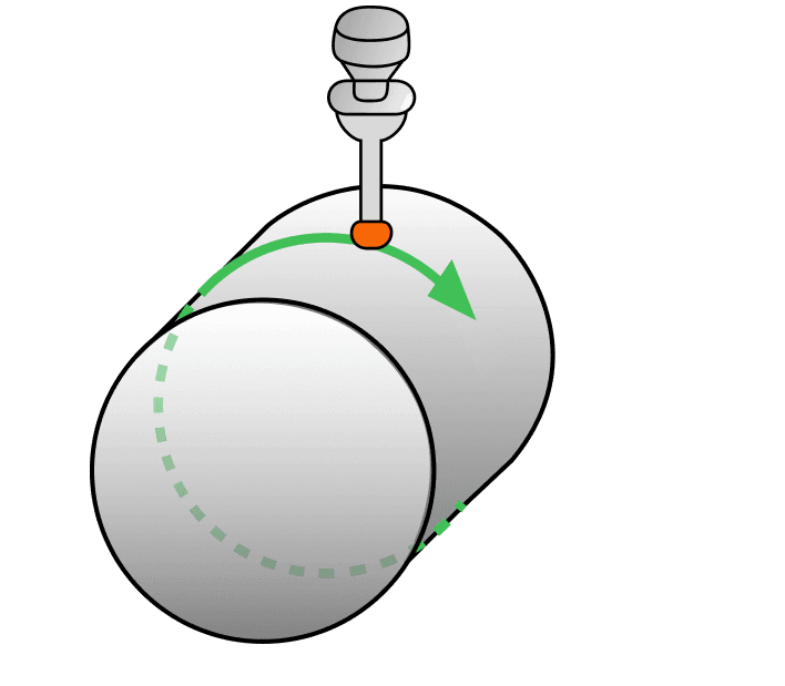
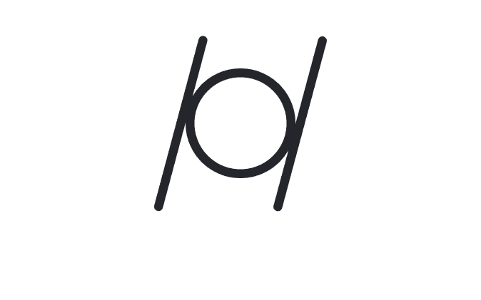
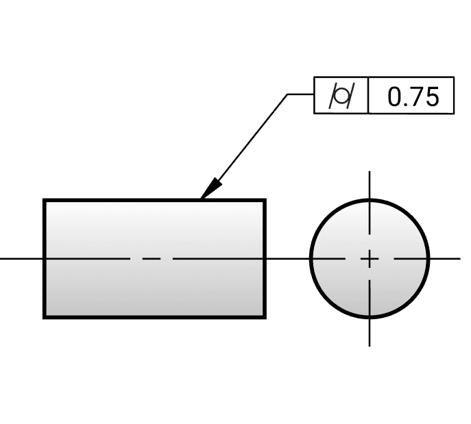
Cylindricity in GD&T is a form tolerance used to control the overall shape of a cylindrical feature. It ensures the surface lies within two coaxial cylinders over the full length of the feature and is evaluated without reference to any datum. Cylindricity combines the requirements of circularity and straightness to control the overall form of a cylindrical feature.
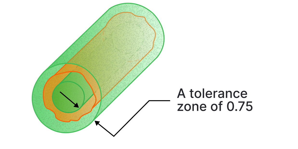
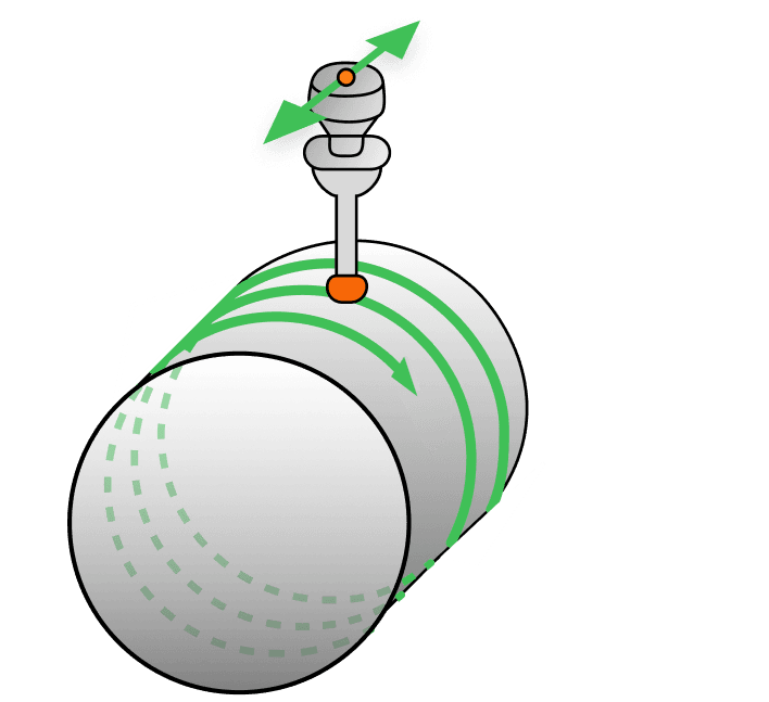
How a feature sits relative to a datum. All three take a datum reference, and all three control the form of a surface as a side effect of controlling its attitude.
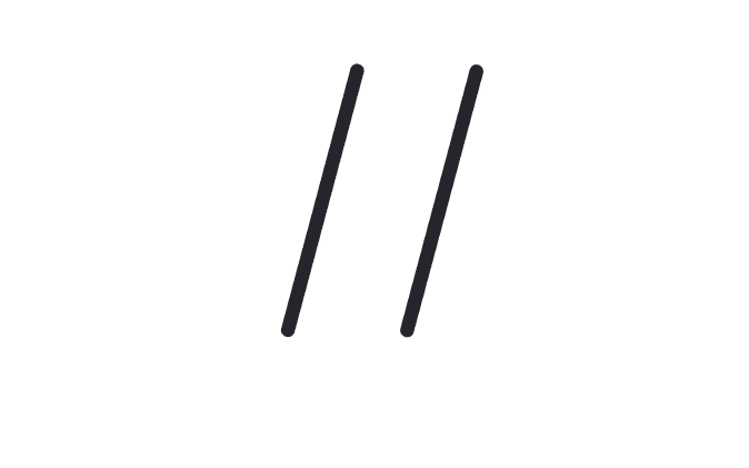
Parallelism in GD&T ensures that a referenced feature maintains a parallel orientation to a specified datum within a 3D tolerance zone. The views below show surface control. Parallelism can also apply to a feature of size, where the derived median plane or line is controlled.
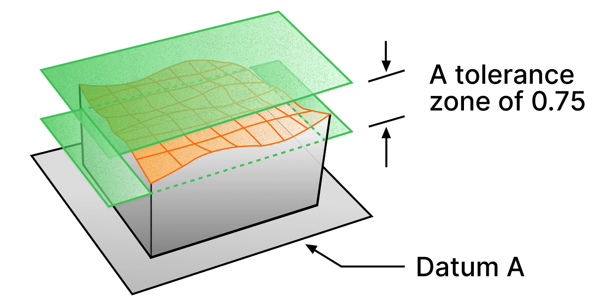
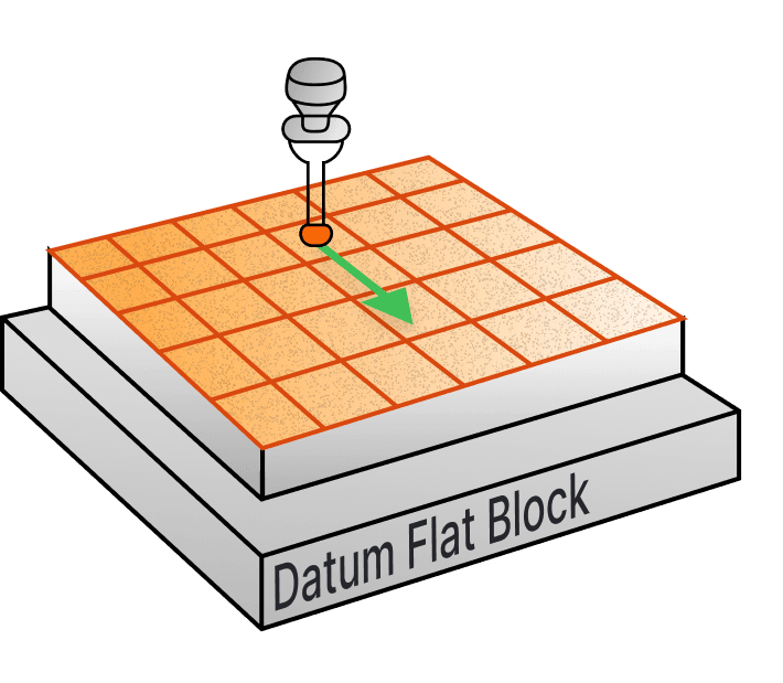
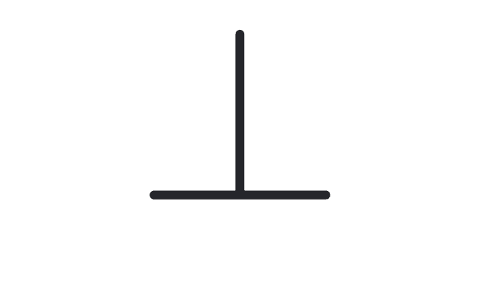
Perpendicularity in GD&T is an orientation tolerance that ensures a surface or axis is at a 90 degree angle to a specified datum. It can be applied to control the perpendicularity of a surface feature or the axis of a cylindrical feature relative to a datum. The views below show surface control. Perpendicularity can also apply to a feature of size, where the derived median plane or line is controlled.
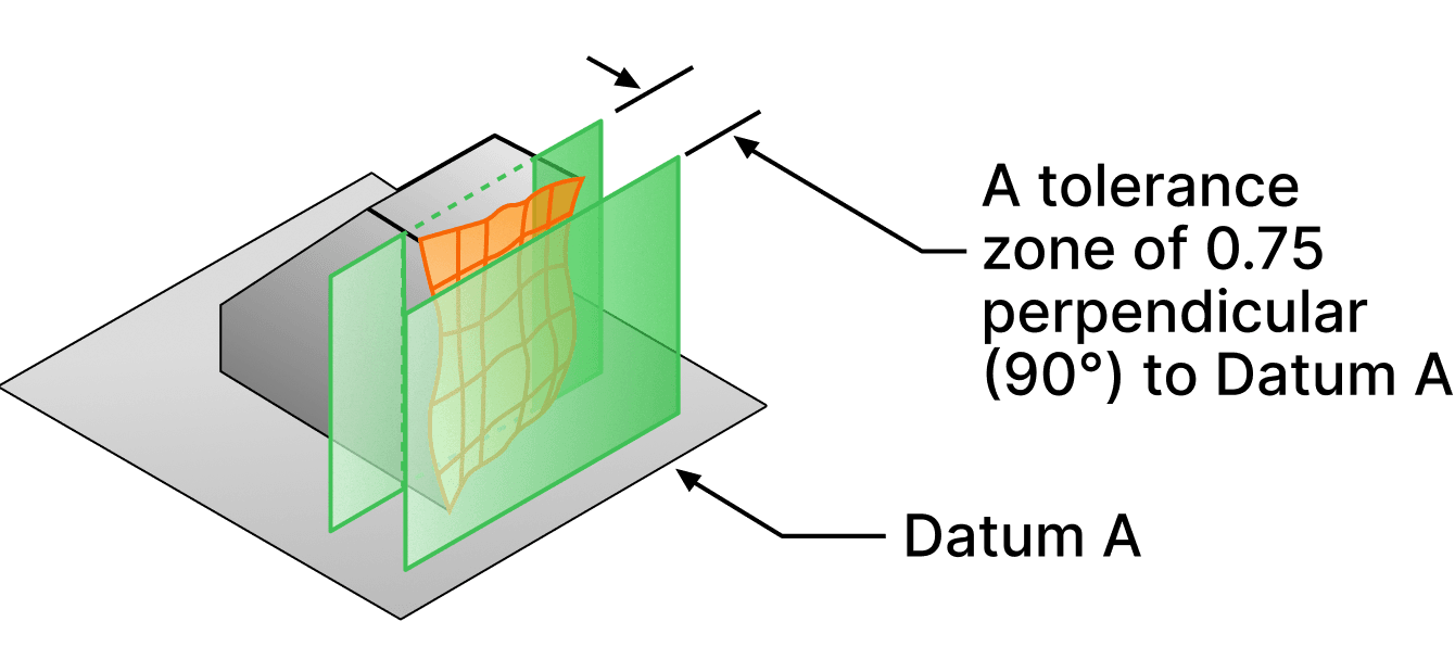
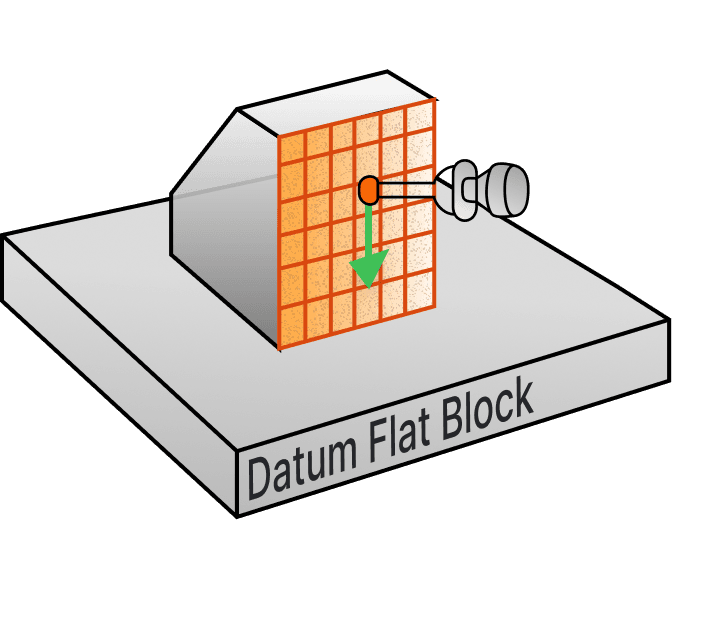
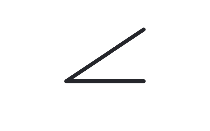
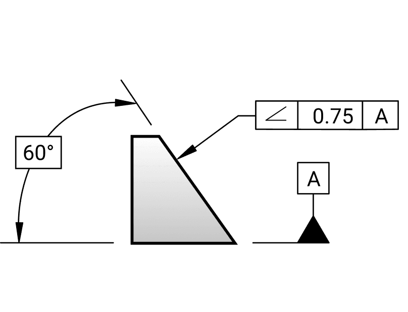
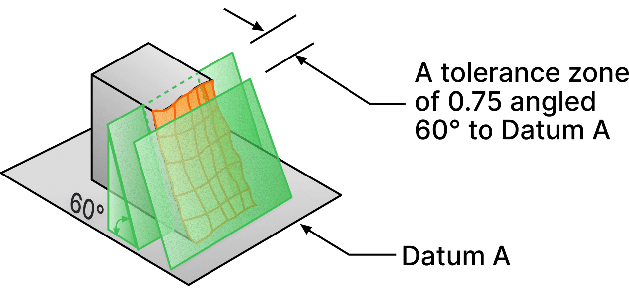
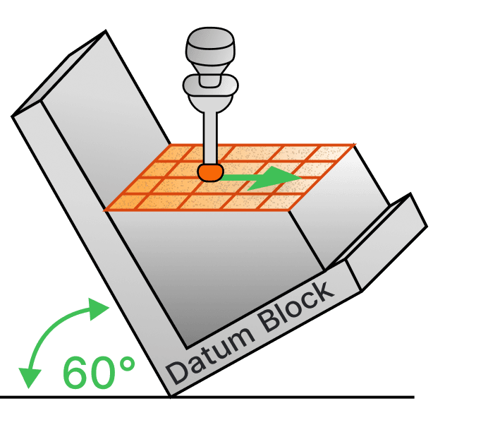
Angularity in GD&T is a symbol that defines the orientation of one feature relative to another at a specified angle within a 3D tolerance zone. The views below show surface control. Angularity can also apply to a feature of size, where the derived median plane or line is controlled.
The one characteristic that can control size, form, orientation and location at once, which is why it stands in for several of the others on a curved surface.
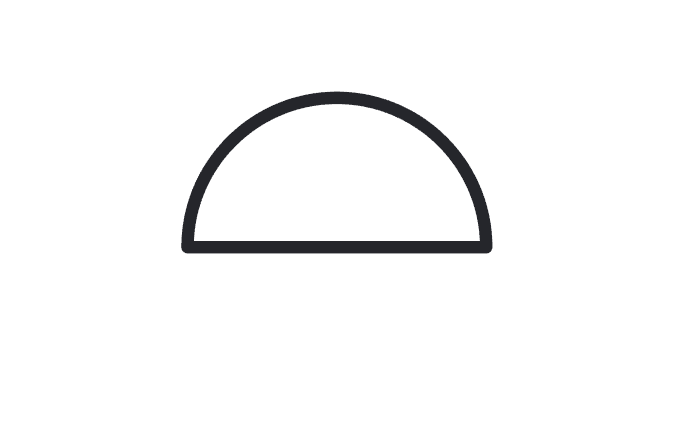
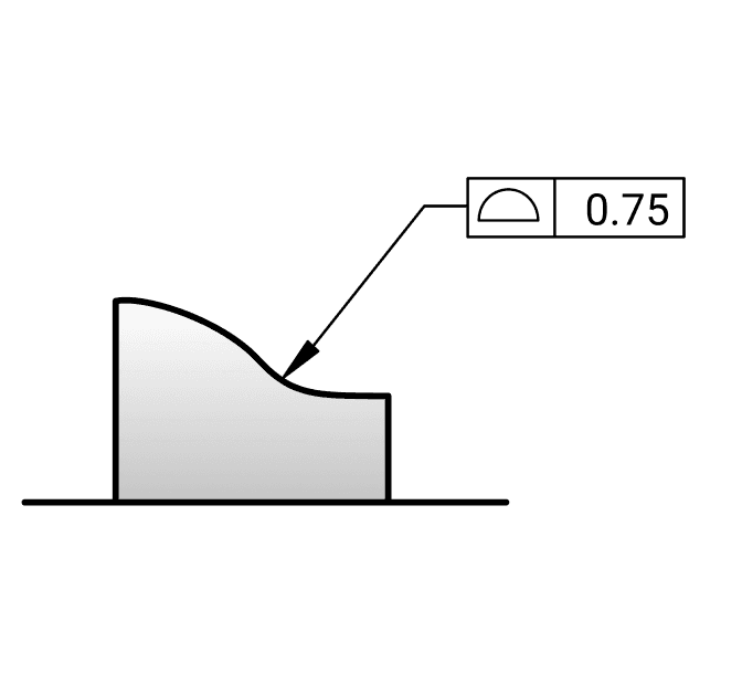
Profile in GD&T defines a 3D tolerance zone around a surface, ensuring that every point along the surface conforms to the specified profile tolerance within a given tolerance. Profile can be used with or without a datum reference frame present.
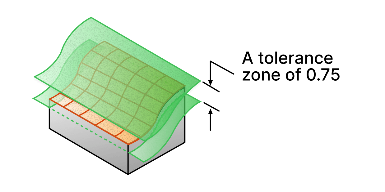
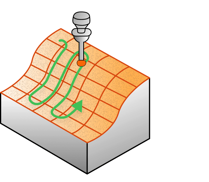
Where the feature actually is, against where the basic dimensions said it would be. This is the one you reach for on a hole pattern.
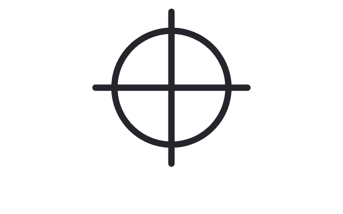
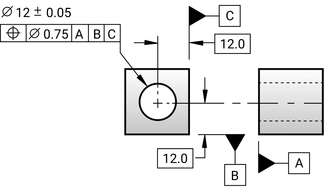
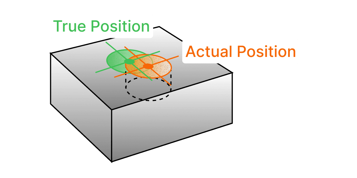
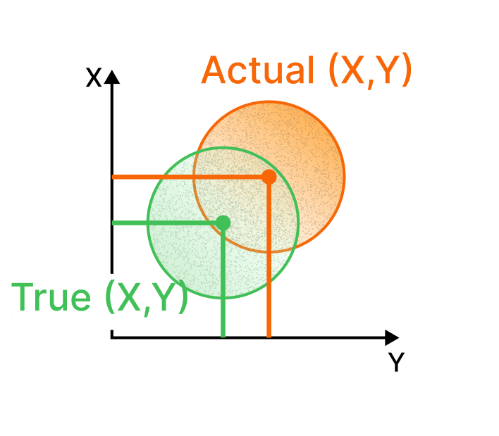
Position in GD&T is a tolerance that defines the allowable deviation of a feature’s location from its nominal, exact position. While it is commonly applied to control the location of a feature of size, it can also be used to control the position of two surfaces relative to one another, depending on the application.
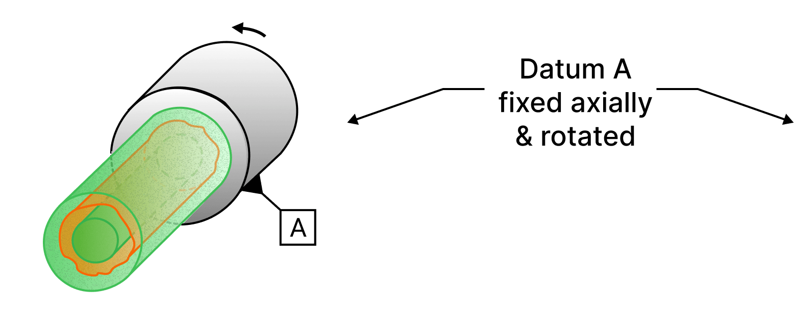
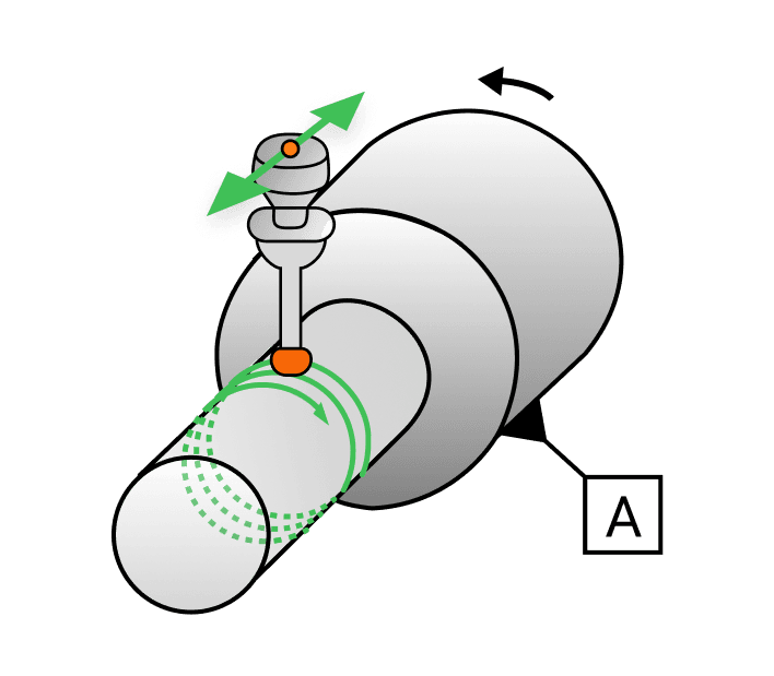
What an indicator reads while the part turns on its datum axis. Circular runout judges one cross section at a time, total runout the whole surface at once.
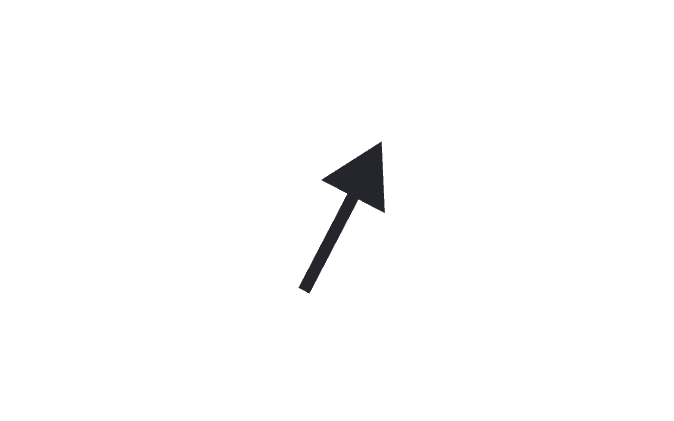
Circular runout is a GD&T tolerance that controls the cumulative variation of form and coaxiality as the part is rotated around a datum axis, ensuring a 2D cross section is within a specified tolerance zone.
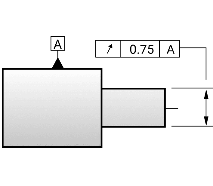
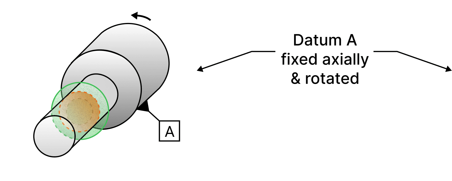
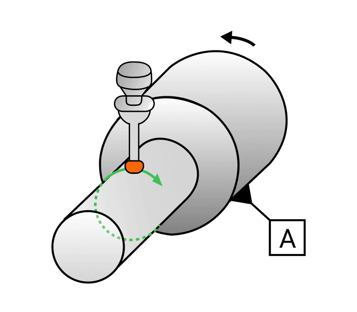
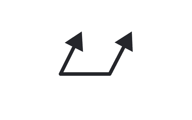
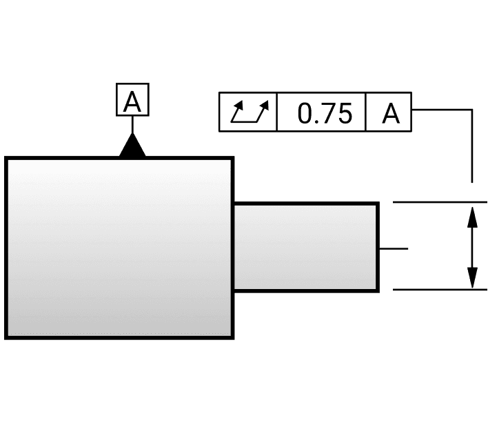
Total runout is a GD&T tolerance that controls the cumulative variations of a surface’s shape, orientation, and position as the part is rotated 360 degrees around a datum axis, ensuring the entire surface remains within a specified tolerance zone.
| Symbol | Name | What it means |
|---|---|---|
| Ⓜ | Maximum material condition (MMC) | MMC is the condition in which a feature of size contains the maximum amount of material, such as the smallest hole size or largest shaft size within the specified tolerance. MMC ensures that parts will fit together even at their worst case tolerances, allowing for additional tolerance in other controlled features. |
| Ⓛ | Least material condition (LMC) | LMC is the condition in which a feature of size contains the least amount of material, such as the largest hole size or smallest shaft size within the specified tolerance. LMC ensures that parts maintain functionality, even when they contain the least material, providing additional tolerance for certain features. |
| All around | All around indicates that a tolerance applies to surfaces all around the perimeter of the view shown. | |
| All over | All over indicates that a given callout applies all over the three dimensional profile of a part. It ensures uniform control across the entire part. | |
| Surface finish | Surface finish indicates the required texture or smoothness of a surface, specifying how rough or smooth a surface must be after manufacturing. It ensures the surface meets functional or aesthetic requirements. | |
| CF | Continuous feature | Continuous feature is used to identify a group of two or more features of size or surfaces where there is a requirement that they will be treated geometrically as a single feature of size or surface. |
| ↔ | Between | Specifies the exact limits of the surface or line that the profile tolerance controls. It indicates that a tolerance or specification applies to a limited segment, or across multiple features. This will be used in conjunction with letter identifiers that indicate placement on the specified part. |
A shop reference, not a standard. This page covers the basic definitions of essential GD&T terminology; for detailed explanations of more advanced concepts, or of geometric symbols used elsewhere such as concentricity and symmetry, refer to ASME Y14.5-2018 or the 2009 standard.
Free download
Print the GD&T sheet for the wall.
The whole cheat sheet on a single page, drawn at poster scale so the symbols stay readable pinned above a desk.
Downloading takes a free Drafter account. One account gets you every chart in the toolbox.