
Reference chart
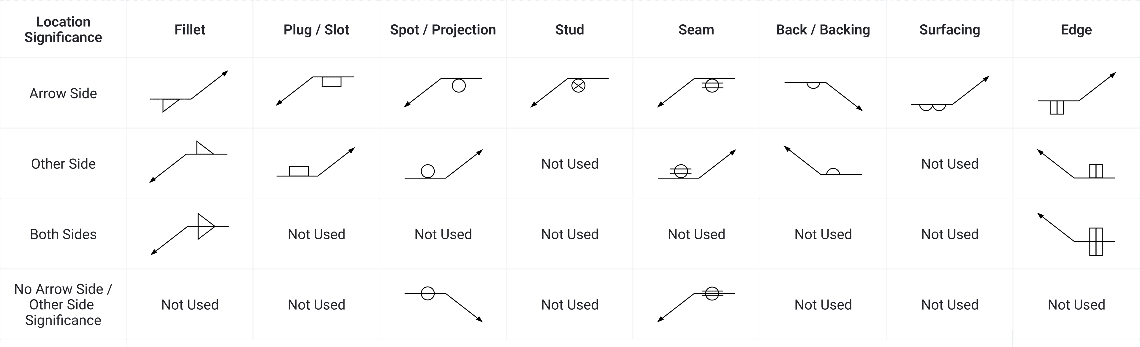
The twenty parts of a weld symbol, then every basic and groove symbol by arrow side, other side and both sides, with the supplementary symbols, the contours and the five basic joints. Written to AWS A2.4.
Free download
Get the weld symbol chart as a PDF.
The whole chart on a single page, drawn at poster scale so the symbols stay readable from a step back.
Downloading takes a free Drafter account. One account gets you every chart in the toolbox.

Weld symbols are standardized graphics used on engineering and fabrication drawings to precisely specify weld type, size, location, and details. Following standards like AWS A2.4, they ensure clear communication between design, fabrication, and inspection teams across industries such as manufacturing, construction, and aerospace, helping maintain quality, code compliance, and structural integrity.
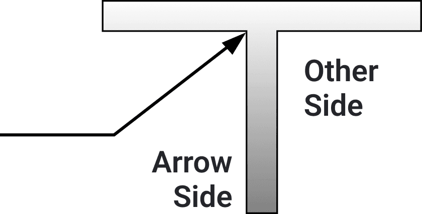
The core of every welding symbol is the reference line, a horizontal line that serves as the base for all weld instructions, including type, size, and length.
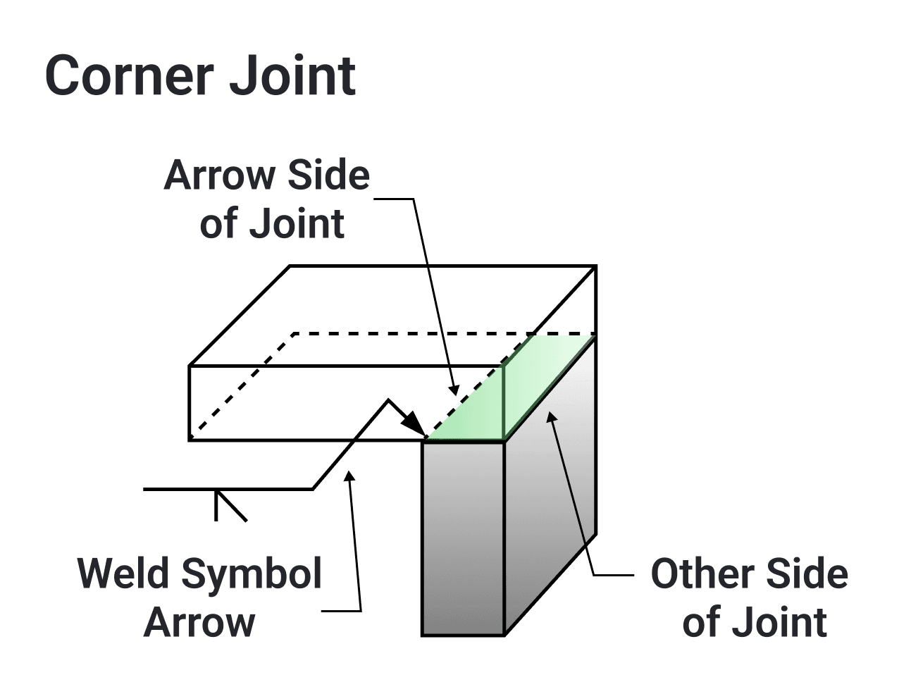
A welded joint typically has two sides, so there are two possible locations for welds. For instance, in a T-joint between two steel plates, welds might be required on either side of the vertical plate. The welding symbol distinguishes these sides using the arrow side and the other side convention, shown here.
| Position on the symbol | What it means |
|---|---|
| Below the reference line | Instructions here apply to the arrow side of the joint. |
| Above the reference line | Instructions here apply to the other side of the joint. |
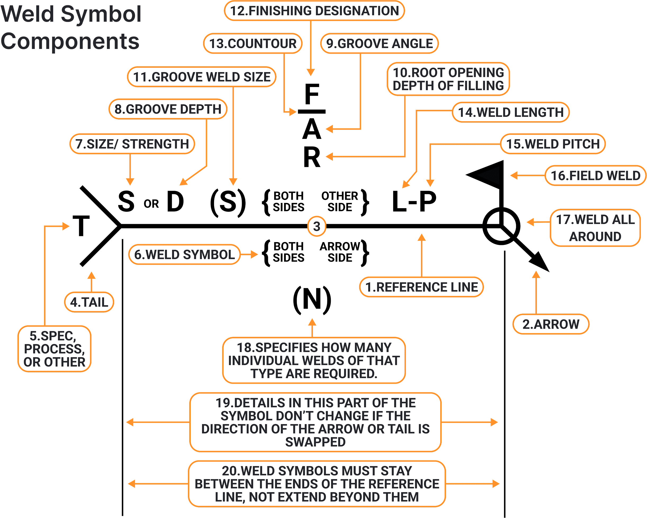
Every position a weld symbol can carry information, numbered to match the callouts on the diagram below.
| # | Callout | What it means |
|---|---|---|
| 1 | Reference line | Main line where weld info is placed |
| 2 | Arrow | Points to joint location for weld |
| 3 | Arrow side / other side / both sides | Specifies weld location relative to arrow |
| 4 | Tail (T) | Optional notes like process, specs, or codes |
| 5 | Spec, process, or other | Text in tail with extra instructions |
| 6 | Weld symbol | Shape indicating weld type (e.g. fillet, groove) |
| 7 | Size / strength (S or D) | Size or strength of weld (e.g. leg size, throat) |
| 8 | Groove depth | Depth of groove prep |
| 9 | Groove angle | Angle between groove faces |
| 10 | Root opening / fill depth | Gap at root or how deep to fill |
| # | Callout | What it means |
|---|---|---|
| 11 | Groove weld size | Throat size for groove welds |
| 12 | Finishing designation | Specifies weld finish method (e.g. grind, machine) |
| 13 | Contour | Final weld surface shape (flat, convex, concave) |
| 14 | Weld length | Length of each weld segment |
| 15 | Weld pitch (L-P) | Spacing between welds |
| 16 | Field weld | Weld done on-site, not in shop |
| 17 | Weld all around | Weld goes completely around joint |
| 18 | (N) | Number of identical welds required |
| 19 | Details don't change with arrow direction | Symbol info stays valid if arrow flips |
| 20 | Symbols stay between reference line ends | Symbols must fit within reference line limits |
Scroll to see every column on a narrow screen.
The same four location rows, crossed with seven groove types and a scarf joint for brazing.
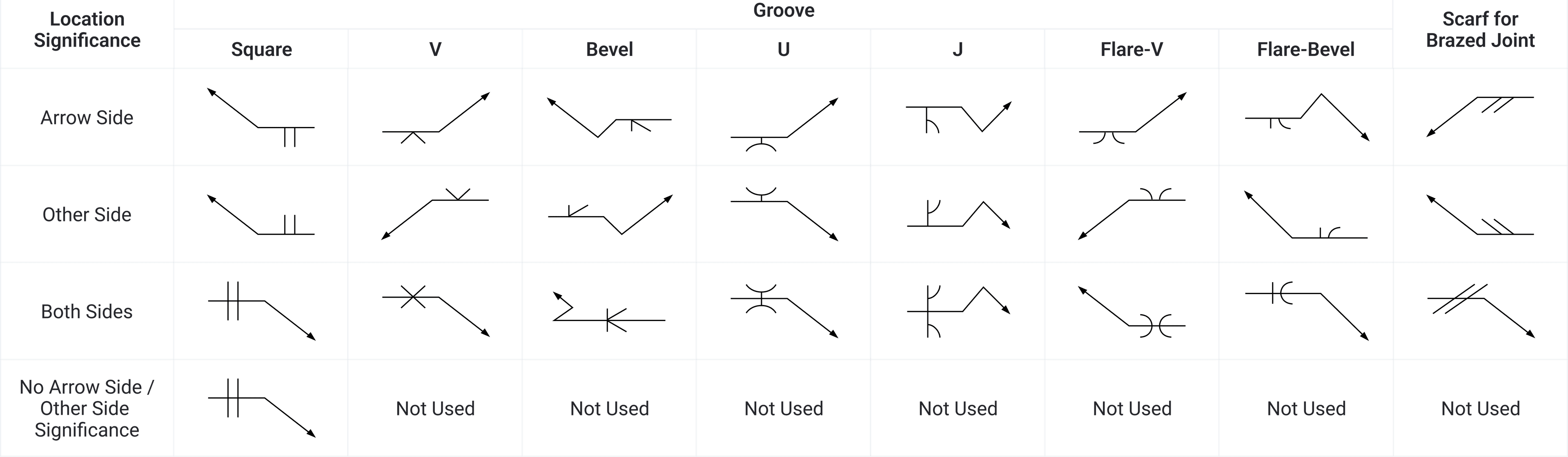
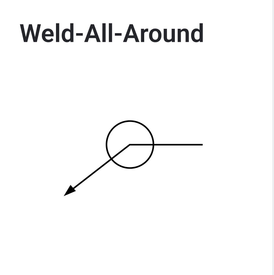
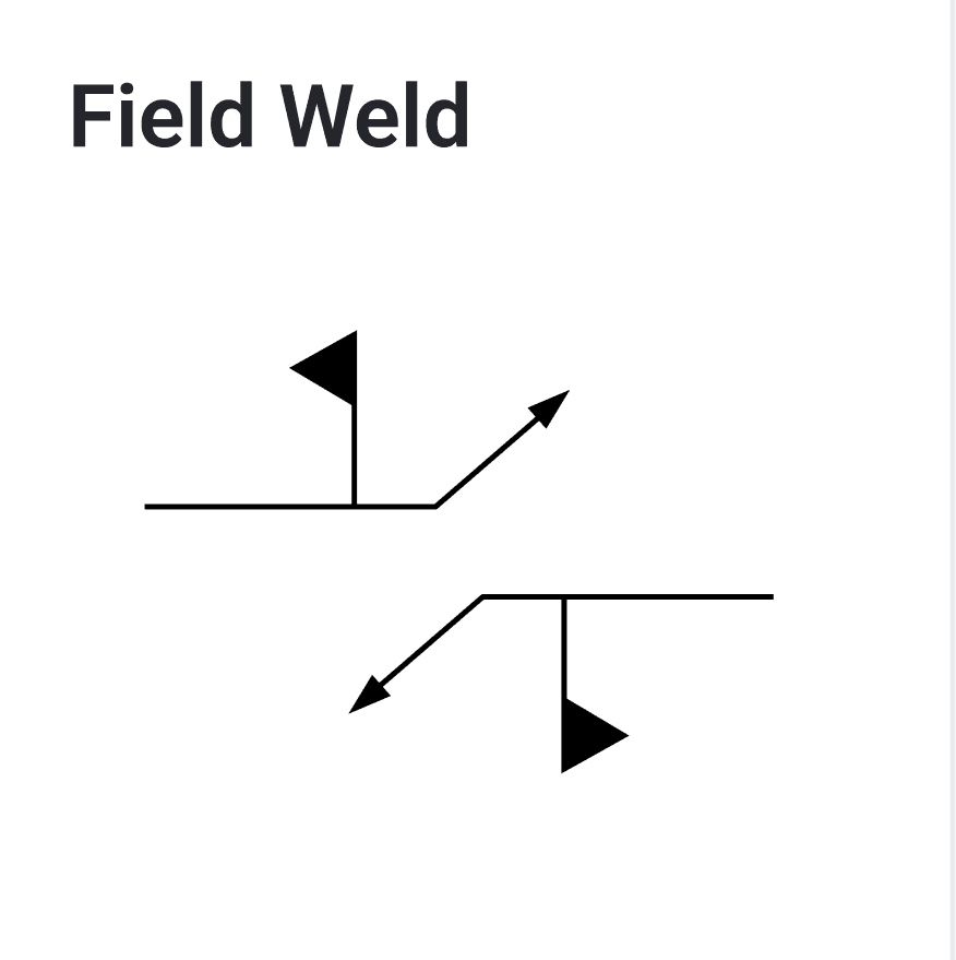
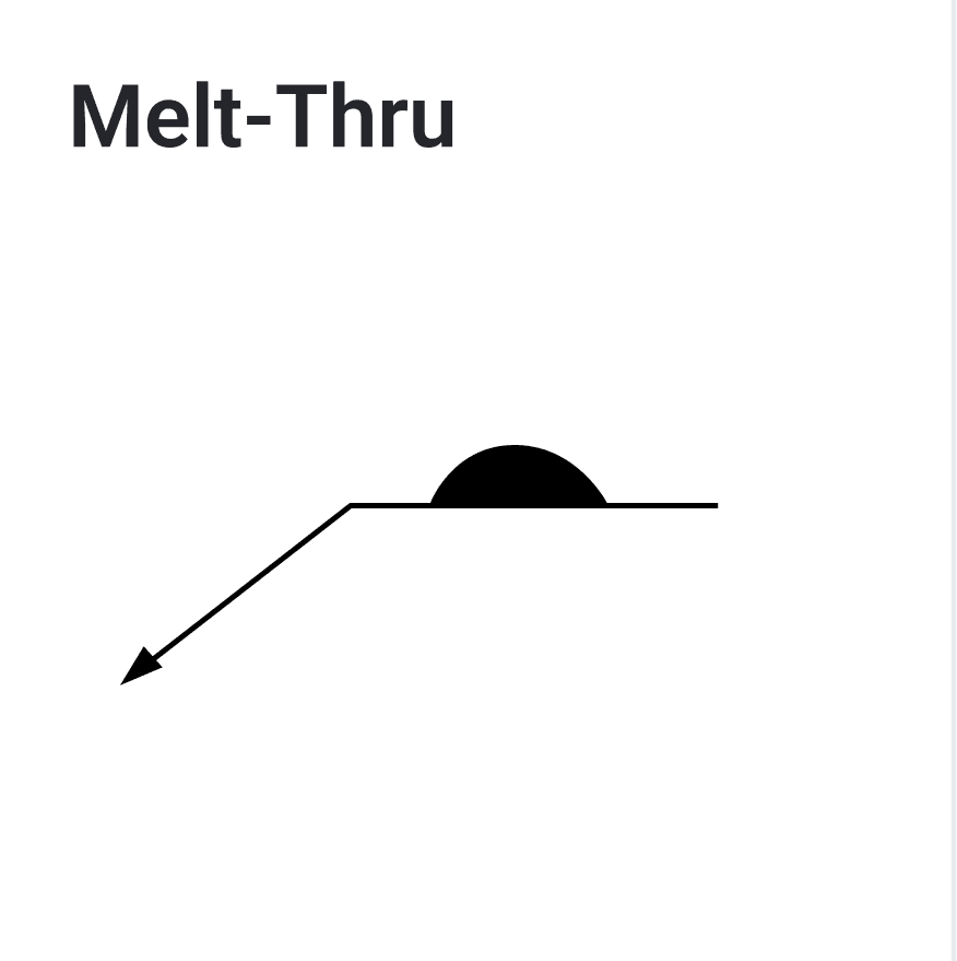
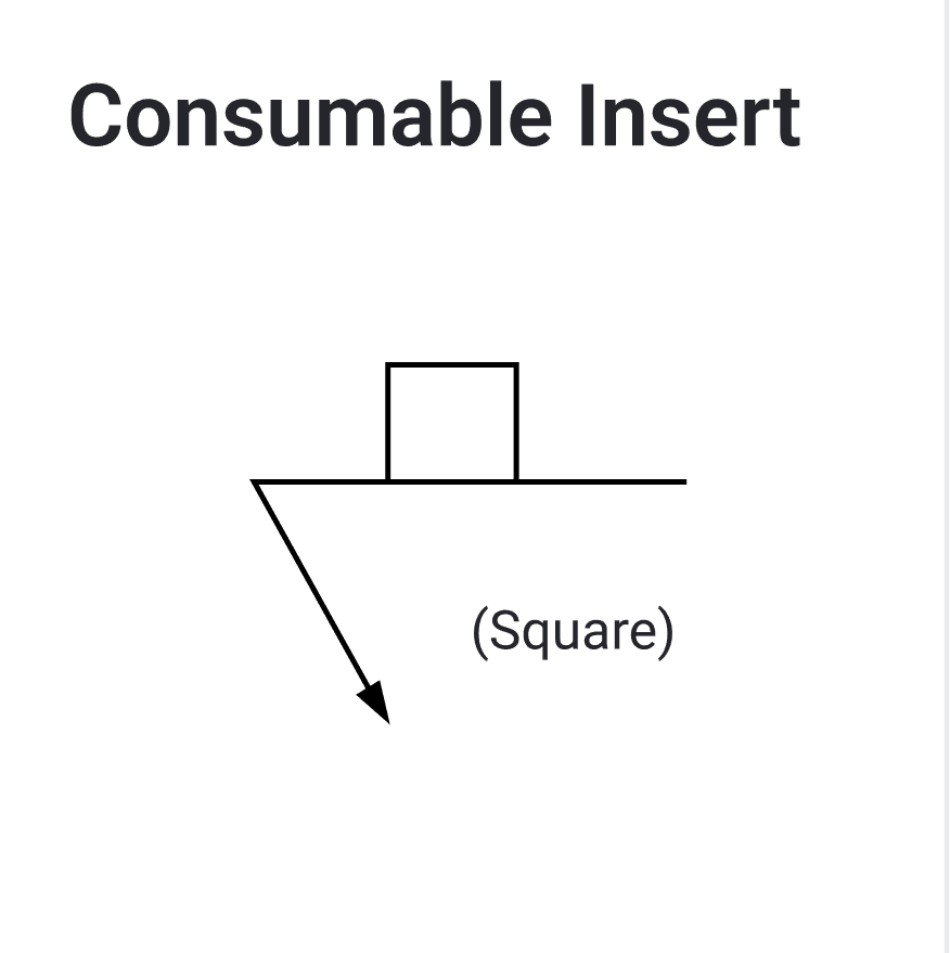
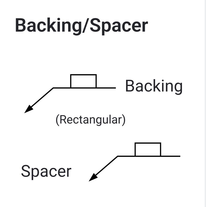
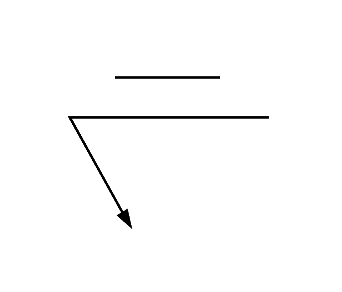
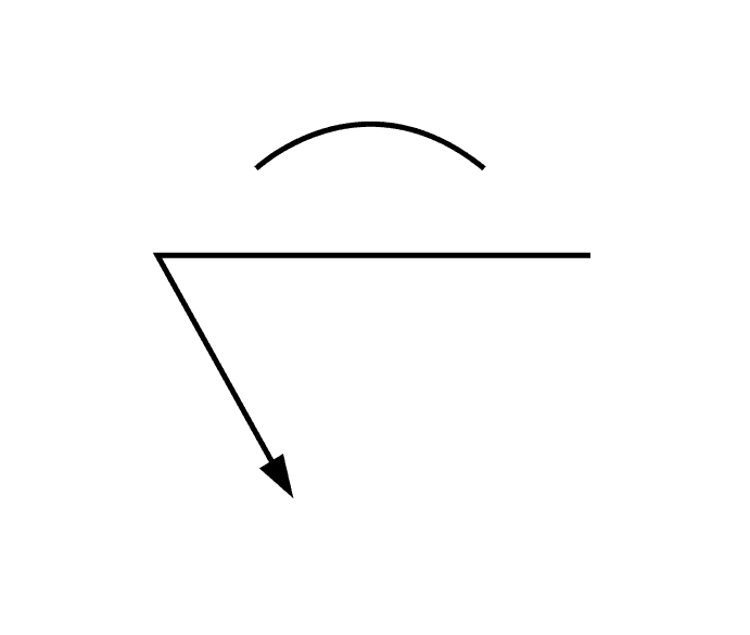
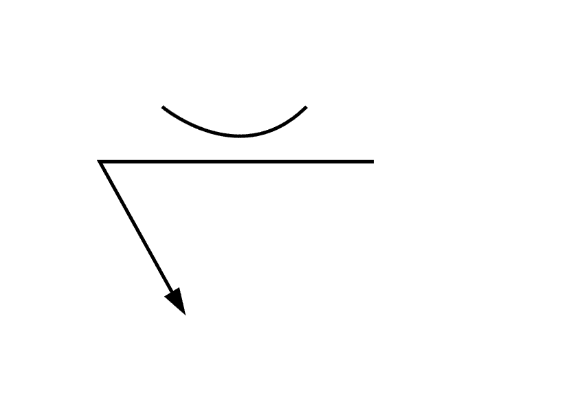
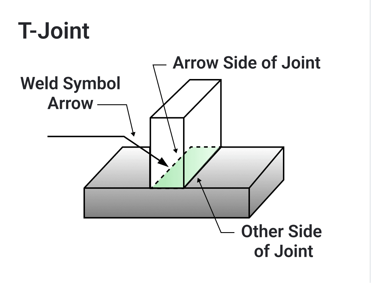
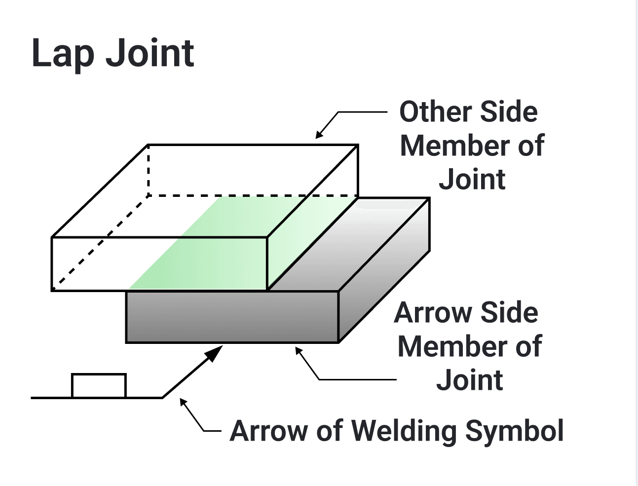
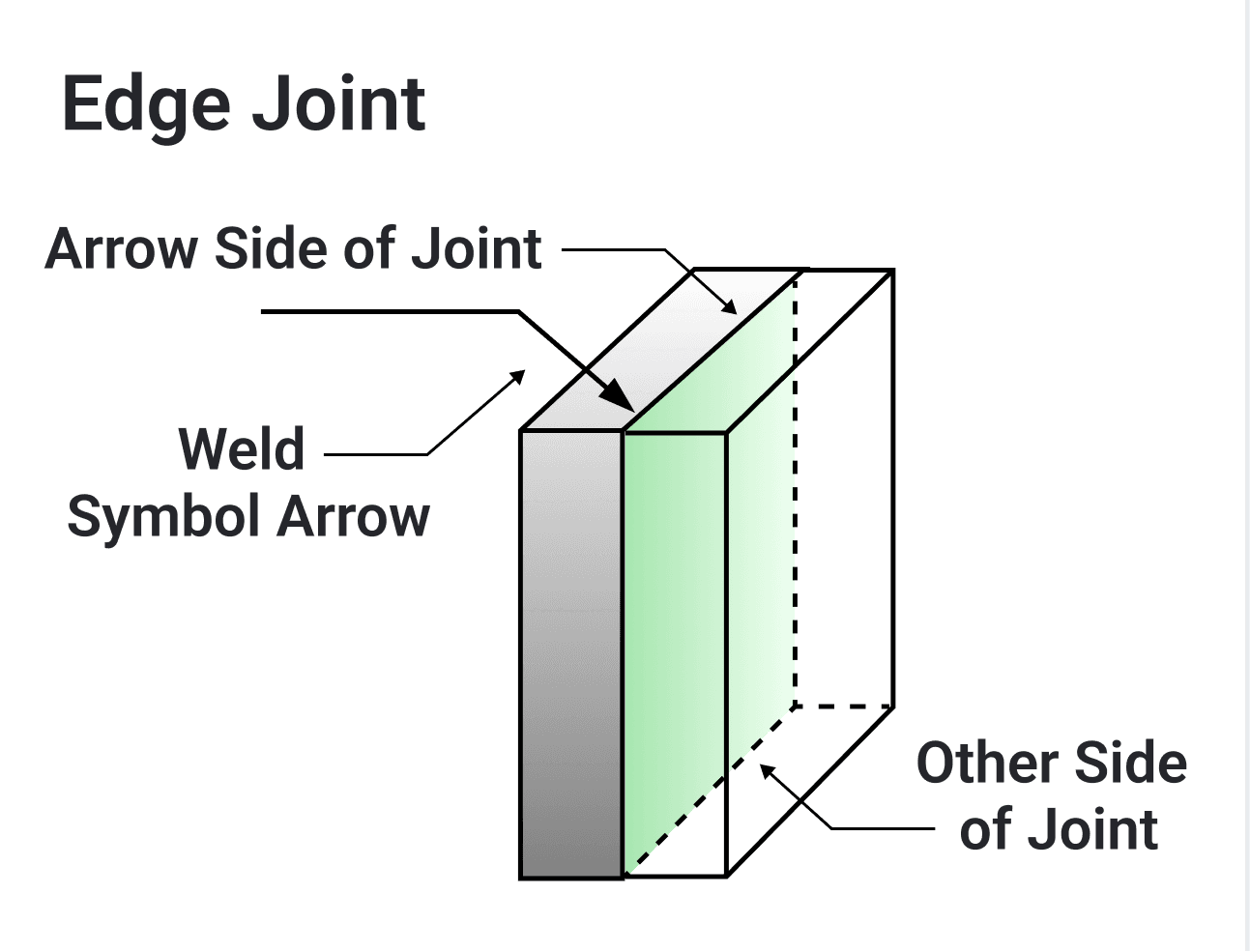
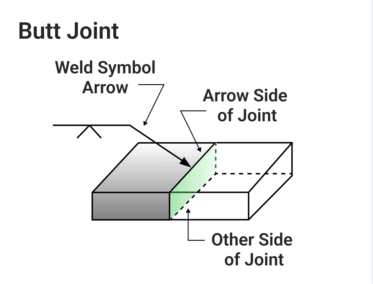
A shop reference, not the standard. This chart covers common basic weld symbols only: for the complete and official specification, refer to AWS A2.4, Standard Symbols for Welding, Brazing, and Nondestructive Examination.
Free download
Print the weld chart for the wall.
The whole chart on a single page, drawn at poster scale so the symbols stay readable from a step back.
Downloading takes a free Drafter account. One account gets you every chart in the toolbox.